News

Switchgear in Modern Power Systems: Technology, Market Dynamics, and Strategic Selection Across Voltage Levels

2026-03-24 0 Leave me a message

Executive Summary


Switchgear is the backbone of every modern electrical power system. From the generator terminals of a power plant to the last distribution panel in a commercial building, switchgear performs the essential functions of switching, protection, isolation, and monitoring that keep power flowing safely and reliably. Without it, neither controlled operation nor safe fault management of electrical networks would be possible.


As global electricity demand grows, power networks become more complex, and the integration of renewable energy sources accelerates, the requirements placed on switchgear are evolving rapidly. Higher short-circuit withstand ratings, smarter protection coordination, digital monitoring integration, and more stringent environmental performance standards are reshaping the specifications demanded by utilities, industrial operators, and infrastructure developers worldwide.


This white paper provides a thorough examination of switchgear technology across voltage classes — from low-voltage distribution switchgear to medium-voltage ring main units and high-voltage metal-enclosed switchgear. It covers the engineering principles underlying each product category, the key performance parameters and standards that govern specification, primary application domains, and a structured procurement methodology to guide technology selection decisions.


Lugao Power Co., Ltd. is a leading China-based manufacturer of the full switchgear voltage range, offering products certified to IEC, ANSI, and IEEE standards with OEM capability, strong custom engineering support, and extensive global export experience. This document also presents Lugao Power's product portfolio, manufacturing capabilities, and competitive positioning as a reliable supply partner for global switchgear projects.


Table of Contents


1. Industry Overview & Market Context


1.1 The Global Electricity Imperative

The global installed electrical generation capacity surpassed 9,000 GW in 2024 and continues to grow at approximately 3% annually. Every watt of that capacity — whether generated by coal, gas, nuclear, hydro, solar, or wind — must pass through switchgear systems multiple times on its journey from generator to consumer. The reliable, safe operation of this switchgear infrastructure is not merely an engineering consideration; it is a prerequisite for the functioning of modern society.


Electricity access, network reliability, and the speed of infrastructure expansion are critical determinants of economic competitiveness. Power outages caused by switchgear failures cost industrial economies billions of dollars annually in lost production and damaged equipment. Conversely, well-designed, properly maintained switchgear systems enable high-availability networks that underpin everything from hospital operations to semiconductor fabrication to data centre services.


1.2 Market Size & Growth Drivers

The global switchgear market was valued at approximately USD 127 billion in 2023 and is projected to grow at a CAGR of 6.8–7.9% through 2030, reaching an estimated USD 200–215 billion. The primary growth drivers include:

  • Grid Modernisation: Aging transmission and distribution infrastructure across North America, Europe, and developed Asia is being replaced with modern, digitally-integrated equipment.
  • Renewable Energy Integration: Solar and wind generation projects require dedicated switchgear for generator step-up, grid connection, and protection coordination.
  • Electrification of Transport: EV charging infrastructure and electric railway expansion are creating substantial new demand for distribution switchgear.
  • Industrial Expansion: Semiconductor fabs, data centres, battery manufacturing, green hydrogen plants, and LNG facilities all require specialised, high-reliability switchgear.
  • Emerging Market Electrification: Sub-Saharan Africa, South and Southeast Asia, and Latin America represent large untapped markets for primary distribution switchgear infrastructure.
  • SF₆ Phase-Out Regulation: The EU's F-Gas Regulation and equivalents globally are mandating replacement of SF₆-insulated switchgear with alternative technologies, triggering a significant replacement cycle.


Region 2023 (USD B) 2030F (USD B) CAGR Primary Driver
Asia-Pacific USD 52.4 USD 87.6 7.6% Industrialisation
Europe USD 28.1 USD 44.8 6.9% Grid upgrade, SF₆ phase-out
North America USD 24.6 USD 39.4 7.0% Aging infra, RE build-out
Middle East & Africa USD 12.3 USD 22.1 8.7% Electrification
Latin America USD 9.6 USD 15.7 7.2% Grid expansion

Table 1 — Global Switchgear Market by Region, 2023–2030 (Indicative)


2. What is Switchgear? Principles & Functions


2.1 Definition

The term "switchgear" refers collectively to the combination of electrical disconnect switches, fuses, circuit breakers, and associated control, protection, metering, and monitoring equipment assembled as a coordinated, integrated system. Switchgear controls, protects, and isolates electrical equipment in power systems. It is the interface between the power network and the loads it serves, and the enforcement mechanism for the protection and control schemes that keep the network safe.


A switchgear assembly may range in physical scale from a single low-voltage distribution board occupying a few hundred millimetres of wall space, to a gas-insulated high-voltage substation spanning thousands of square metres. Despite this range of scale, all switchgear performs the same set of fundamental functions.


2.2 Core Functions

Function Description & Importance
Switching Making and breaking electrical circuits under normal operating conditions. Enables planned network reconfigurations, load transfers, and equipment isolation for maintenance.
Protection Detecting abnormal conditions (overcurrents, short circuits, earth faults, voltage excursions) and initiating rapid circuit interruption to limit equipment damage and prevent cascading failures.
Isolation Creating a proven, visible, safe electrical break in a circuit, enabling personnel to work on de-energised equipment without risk of inadvert re-energisation.
Measurement & Metering Measuring voltage, current, power, energy, power factor, and harmonics for billing, monitoring, load management, and power quality assessment.
Monitoring & Control Providing local and remote visibility of circuit status, alarm conditions, and equipment health; enabling remote switching operations via SCADA or substation automation systems.

Table 2 — The Five Core Functions of Switchgear


2.3 How Circuit Interruption Works

The most critical and technically demanding function of switchgear is fault current interruption. When a short circuit occurs in a power system, fault currents can reach values 10–50 times the normal operating current within milliseconds. If not interrupted rapidly, these fault currents will cause catastrophic thermal and mechanical damage to cables, transformers, and other equipment.


The circuit breaker — the primary interrupting device in a switchgear assembly — must perform three actions in rapid sequence: detect the fault (via associated protection relays), separate the electrical contacts, and extinguish the arc that forms between the separating contacts. The arc extinction mechanism is the key differentiator between different circuit breaker technologies and is discussed in detail in Chapter 7.


2.4 Switchgear vs. Related Equipment

  • Switchgear vs. Controlgear: Switchgear is associated primarily with power circuits (generation, transmission, distribution). Controlgear typically refers to equipment controlling motors and other industrial loads in control circuits. IEC 62271 covers switchgear; IEC 60947 covers low-voltage controlgear.
  • Switchgear vs. Protection Relays: Protection relays detect fault conditions and send trip signals. The switchgear (specifically the circuit breaker) executes the interruption. The relay commands the breaker.
  • Switchgear vs. Transformer: A transformer changes voltage levels; switchgear controls and protects circuits. In a substation, both co-exist as distinct functional components.


3. Switchgear Classification by Voltage Level

The most fundamental classification of switchgear is by the voltage level at which it operates. Voltage level determines the required insulation clearances, arc energy levels, equipment dimensions, and applicable standards. The industry standard voltage classification is:


Voltage Class Voltage Range Typical Applications Primary Standards
Low Voltage (LV) Up to 1,000 V AC Building distribution, motor control, industrial panels IEC 61439, IEC 60947, UL 508A
Medium Voltage (MV) 1 kV – 52 kV Primary distribution, industrial supply, RE projects IEC 62271-100 / -200 / -202
High Voltage (HV) 52 kV – 800 kV Transmission substations, grid interconnections IEC 62271-100 / -203, IEEE C37
Ultra-High Voltage (UHV) Above 800 kV Long-distance HVDC/HVAC transmission backbone IEC 62271 (special)

Table 3 — Switchgear Classification by Voltage Level


Note: Definitions of "medium voltage" and "high voltage" vary between standards bodies and regional conventions. In IEC terminology, HV covers all voltages above 1 kV, with a further distinction between "high voltage" (1–52 kV, sometimes called MV by practitioners) and "extra-high voltage" (EHV) above 52 kV. This white paper uses the practitioner convention: LV ≤1 kV; MV = 1–52 kV; HV = 52–800 kV.


3.1 Additional Classification Dimensions

Beyond voltage level, switchgear is also classified along several other important dimensions:


Dimension Categories
Insulation Medium Air-insulated (AIS), Gas-insulated SF₆ (GIS), Vacuum, Oil (legacy), Solid dielectric
Enclosure Type Metal-enclosed, Metal-clad, Cubicle-type, Open-type (outdoor)
Interrupting Medium Air blast, Oil, Vacuum, SF₆, CO₂ / clean air (emerging)
Indoor / Outdoor Indoor switchgear (controlled environment); Outdoor switchgear (weatherproof construction)
Fixed / Withdrawable Fixed-mounted circuit breakers (lower cost, less flexibility) vs. withdrawable/draw-out breakers (easier maintenance, hot-replacement)

Table 4 — Additional Switchgear Classification Dimensions


4. Low-Voltage (LV) Switchgear


4.1 Overview & Scope

Low-voltage switchgear operates at system voltages up to 1,000 V AC (or 1,500 V DC), covering the final stage of power distribution to end-users. LV switchgear is the most numerous by unit count of any switchgear category — literally billions of units are installed worldwide in residential, commercial, and industrial buildings, data centres, hospitals, and manufacturing facilities. Despite its lower voltage level, LV switchgear is not simple; modern LV systems must manage large fault currents, complex harmonic environments, high densities of connected loads, and increasingly sophisticated power quality and energy management requirements.


4.2 Key Components of LV Switchgear Assemblies

A low-voltage switchgear and controlgear assembly (LVSCA), defined by IEC 61439, typically incorporates the following functional components:


  • Moulded Case Circuit Breakers (MCCBs): The workhorse protection device for most LV distribution circuits. MCCBs provide overcurrent and short-circuit protection for currents up to approximately 2,500 A. Thermal-magnetic trip mechanisms are standard; electronic trip units are used in higher-performance variants.
  • Air Circuit Breakers (ACBs): Used for main incomer and bus-coupler applications in large LV distribution boards where rated currents exceed 800 A (up to 6,300 A). Fully withdrawable construction enables safe maintenance.
  • Miniature Circuit Breakers (MCBs): Compact protective devices rated up to approximately 125 A, widely used in final distribution boards.
  • Residual Current Devices (RCDs/RCCBs): Detect imbalance between phase and neutral currents, providing essential protection against electric shock.
  • Fused Disconnectors and Switch-Fuses: Combine isolation and fuse protection, offering a cost-effective alternative in certain applications.
  • Busbars: Copper or aluminium conductors distributing power across circuits; critical for short-circuit withstand performance.
  • Protection Relays & Measurement Devices: Include overcurrent, earth fault, and multifunction relays, as well as power meters and quality monitors.

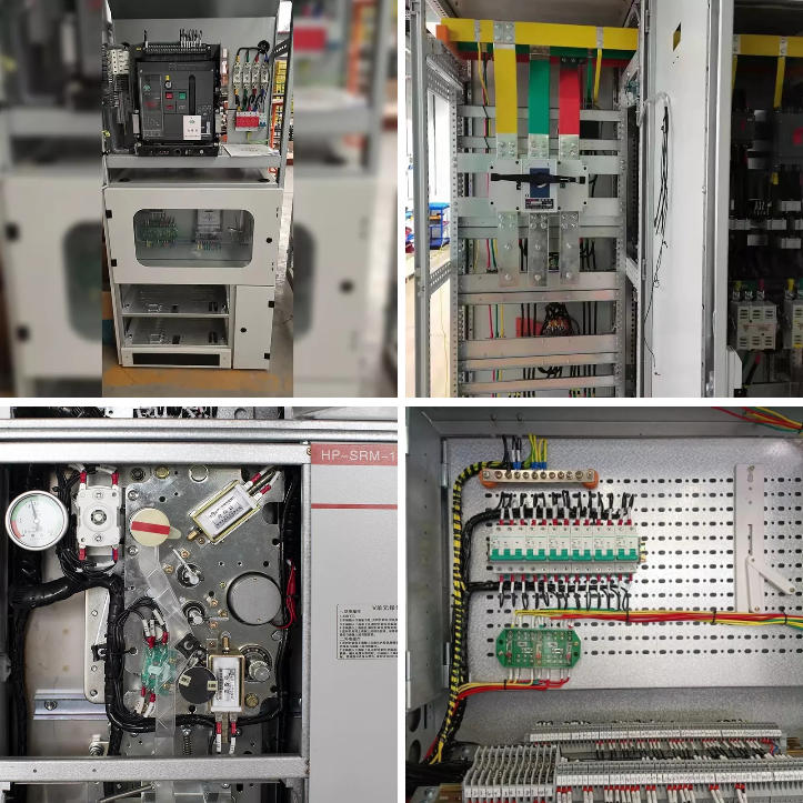
400V Low Voltage Withdrawable Enclosed Switchgear

Figure 1 — Low-Voltage Main Distribution Switchgear

4.3 LV Assembly Types

IEC 61439 defines several types of low-voltage switchgear and controlgear assemblies (LVSCAs) based on their construction and functional characteristics:

  • Main Distribution Boards (MDB): Primary LV distribution point receiving power from transformers and distributing to sub-boards and major loads. Typically 800 A to 6,300 A.
  • Sub-Distribution Boards (SDB): Distribute power to specific zones such as building floors or production areas. Typically 160 A to 1,600 A.
  • Motor Control Centres (MCC): Designed for motor control applications, integrating starters, contactors, protection, and control devices.
  • Power Factor Correction (PFC) Panels: Use capacitor banks to improve power factor, reduce penalties, and enhance system efficiency.


4.4 Key LV Switchgear Performance Parameters

Parameter Description & Typical Values
Rated Voltage (Ue) The operating voltage of the assembly. Common values: 230/400 V, 400/690 V, 1,000 V.
Rated Current (In) Maximum continuous current the assembly can carry without exceeding temperature limits. Range: 63 A to 6,300 A.
Short-Circuit Withstand (Icw) Peak and short-time withstand current. Typical values: 25 kA, 50 kA, 80 kA (1 s or 3 s).
Breaking Capacity (Icu / Ics) Ultimate (Icu) and service (Ics) short-circuit breaking capacity of circuit breakers. Must exceed maximum prospective fault current at installation point.
Degree of Protection (IP) IP3X minimum for indoor industrial; IP54 or IP65 for outdoor or harsh environments per IEC 60529.
Form of Internal Separation IEC 61439 Forms 1–4b define separation between functional units and busbars. Higher forms improve safety and fault containment.

Table 5 — Key LV Switchgear Technical Parameters


5. Medium-Voltage (MV) Switchgear & Ring Main Units


5.1 Overview & Role in the Distribution Network

Medium-voltage switchgear operates in the range of 1 kV to 52 kV and represents the primary switching and protection level for power distribution networks. It is found at the secondary terminals of bulk transmission substations, in primary distribution substations, in large industrial facilities, at the connection point of renewable energy plants, and within box-type transformer substations. MV switchgear determines the fault clearance speed, protection selectivity, and operational flexibility of the distribution network.


The MV segment is undergoing the most significant technology transformation of any switchgear category, driven by the phase-out of SF₆ gas, the integration of digital protection and monitoring, and the demands of smart grid architectures.


5.2 MV Switchgear Construction Types

Construction Type Characteristics & Applications
Metal-Enclosed Switchgear All live parts enclosed within an earthed metal enclosure, with separate compartments for busbars, switching devices, and cable connections. Standard for modern indoor MV installations (IEC 62271-200).
Metal-Clad Switchgear A sub-category with full metallic barriers between all live parts and compartments. Highest level of internal fault containment (IEC 62271-200 LSC2B).
Cubicle-Type Switchgear Non-arc-resistant cubicle panels assembled into lineups. More economical but with lower arc fault performance.
Gas-Insulated Switchgear (GIS) All live parts enclosed in sealed SF₆-filled or alternative gas enclosures. Highly compact, suitable for space-constrained installations.
Air-Insulated Switchgear (AIS) Uses air insulation within metal enclosures or open structures. Larger footprint but simpler and cost-effective.

5.3 Ring Main Units (RMU)


The Ring Main Unit (RMU) is a compact, factory-sealed MV switchgear assembly designed for ring-feed distribution networks — the standard topology for urban and suburban MV cable systems. An RMU typically provides two ring-feeder switch positions plus one or more transformer feeder positions with protection devices.

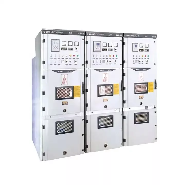
12kV Ring Main Unit SF6 Gas Insulated Switchgear

Figure 2 — Ring Main Unit (RMU): Compact MV Switchgear for Distribution Networks


RMUs are available in two primary insulation variants:

  • SF₆ Gas-Insulated RMU: Uses sulphur hexafluoride gas for insulation and arc-quenching within a sealed tank. Extremely compact and maintenance-free but subject to environmental regulations due to high GWP.
  • Solid-Insulated / Vacuum RMU (SI RMU): Uses solid dielectric materials and vacuum interrupters. SF₆-free, environmentally friendly, and increasingly adopted as a next-generation solution.

5.4 MV Circuit Breaker Technologies

Technology Operating Principle Key Advantages Limitations
Vacuum CB Arc quenched in high-vacuum interrupter bottle Long life (>10,000 operations), no gas, compact, low maintenance Limited to ≤52 kV
SF₆ CB Gas flow extinguishes arc in pressurised chamber High interrupting capacity, excellent insulation, compact High GWP (~23,500), environmental concerns, gas monitoring required
Air-Blast CB High-pressure air extinguishes arc No hazardous gas, suitable for outdoor use Large size, high maintenance, largely obsolete

Table 6 — MV Circuit Breaker Technology Comparison


5.5 MV Switchgear Technical Specifications

Parameter Typical Range / Values
Rated Voltage 3.6 kV, 7.2 kV, 12 kV, 17.5 kV, 24 kV, 36 kV, 40.5 kV, 52 kV
Rated Normal Current 630 A, 1,250 A, 1,600 A, 2,000 A, 2,500 A, 3,150 A, 4,000 A
Short-Circuit Breaking Current 12.5 kA, 16 kA, 20 kA, 25 kA, 31.5 kA, 40 kA, 50 kA
Short-Time Withstand Typically 1 s or 3 s at rated short-circuit current
Lightning Impulse Withstand (LIWV) 60 kV (7.2 kV class) to 250 kV (52 kV class), per IEC 62271-1
Operating Mechanism Spring-charged motor (standard); manual or solenoid options
Applicable Standard IEC 62271-100, IEC 62271-200, GB/T 3906, ANSI C37.20

Table 7 — MV Switchgear Technical Specifications


6. High-Voltage (HV) Switchgear


6.1 Role in Transmission Networks

High-voltage switchgear operates at system voltages above 52 kV, with commonly used voltages of 72.5 kV, 145 kV, 245 kV, 420 kV, and 550 kV. This equipment forms the critical switching and protection infrastructure of the bulk transmission network — the highest-energy tier of the power system, responsible for transporting large quantities of electrical energy over long distances between generation centres and regional load centres.


The consequences of HV switchgear failure are severe: a single faulty circuit breaker at a major 220 kV transmission substation can disconnect hundreds of megawatts of generation or load. Equipment damage from fault currents at HV levels can be catastrophic and costly. This context explains the extremely demanding performance and rigorous testing requirements that HV switchgear must satisfy.


6.2 HV Switchgear Technologies

6.2.1 Air-Insulated Substations (AIS)

In AIS technology, HV switchgear components — circuit breakers, disconnectors, earthing switches, instrument transformers — are installed in open-air structures with air providing insulation between live parts and earth. AIS substations have been the standard for transmission-level switching for decades and remain common globally due to simplicity, lower cost, and ease of maintenance and inspection.

AIS substations require significant land area to maintain safety clearances. A typical 220 kV AIS substation may require 1–3 hectares, with several metres of clearance between phases and to earth.

6.2.2 Gas-Insulated Substations (GIS)

In GIS technology, all live components are housed within sealed, SF₆-gas-filled cylindrical aluminium enclosures. The superior dielectric properties of SF₆ allow phase-to-earth and phase-to-phase clearances to be drastically reduced, shrinking the substation footprint to 10–15% of the equivalent AIS area.

GIS is preferred in space-constrained environments such as urban underground substations, offshore platforms, high-altitude sites, and heavily polluted industrial areas.

Armored Removable AC Metal Enclosed Switchgear

Figure 3 — High-Voltage Gas-Insulated Switchgear (GIS) Transmission Substation 


6.2.3 Hybrid Switchgear (HGIS)

Hybrid switchgear integrates multiple primary functions (circuit breaker, disconnector, earth switch, current transformer) within a single compact SF₆-filled module. This offers intermediate footprint reduction between AIS and GIS, at a cost between the two. HGIS is increasingly used in brownfield extensions and capacity additions where full GIS is cost-prohibitive.


6.3 HV Circuit Breaker Technologies

The SF₆ puffer-type or self-blast circuit breaker is the dominant HV technology. Improvements in contact geometry and arc control reduce operating energy, enabling reliable spring-actuated mechanisms instead of large hydraulic/pneumatic actuators. Phased SF₆ alternatives for HV (CO₂/O₂ mixtures, vacuum interrupters) are still under research, with limited commercial deployment as of 2026.

6.4 Lugao HV Switchgear — Specifications

Parameter Lugao HV Switchgear Specification
Voltage Range 3,600 V – 40,500 V (compliant with IEC 62271-1 voltage class definitions)
Rated Normal Current Up to 4,000 A
Short-Circuit Withstand Up to 50 kA (1 s short-time withstand)
Enclosure Type Fully insulated metal-enclosed cabinet; indoor and outdoor configurations
Insulation Medium Air-insulated (AIS) / Solid-insulated; SF₆ configurations available
Standards Compliance IEC 62271-100, IEC 62271-200, IEC 62271-1, GB/T 3906, ANSI/IEEE C37 Series
Certifications CE, ISO, CCC; Third-party type-tested

Table 8 — Lugao Power HV Switchgear Technical Specifications


7. Insulation & Arc-Quenching Technologies


7.1 The Arc Problem

When circuit breaker contacts separate under load or fault current, the electrical energy sustains a plasma arc between contacts. Temperatures reach 5,000–20,000 K, carrying full fault current until extinguished. The arc-quenching capability of the breaker — speed to interrupt at a natural current zero — determines maximum interruptible fault current (breaking capacity) and energy let-through.


Interrupting media, contact geometry, and operating mechanism design define breaker performance and maintenance requirements.


7.2 Arc-Quenching Media Comparison

Medium Voltage Range Breaking Performance Environmental Impact Maintenance Trend
Vacuum LV – 52 kV Excellent None Very low Growing
SF₆ Gas MV – HV Excellent GWP 23,500 ⚠ Low (sealed) Regulated ↓
Air (ACB) LV Good None Moderate Stable
Oil (Bulk) MV (legacy) Good Fire risk High Legacy ↓
CO₂ Mixture MV–HV (dev) Emerging GWP ~1 TBD R&D Phase

Table 9 — Arc-Quenching Media Comparison Across Switchgear Categories


7.3 Insulation Technologies

  • Air Insulation (AIS): Ambient air as dielectric. Simple, cost-effective, requires large clearances, sensitive to pollution, humidity, and altitude.
  • SF₆ Gas Insulation (GIS): Pressurised SF₆ in sealed enclosures. Compact, 10–15× smaller clearances than AIS. SF₆ phase-out due to GWP ≈ 23,500.
  • Solid Dielectric Insulation: High-performance polymers (epoxy, EPDM, cycloaliphatic resin). SF₆-free alternative, pollution-resistant, rapidly gaining market share in MV switchgear and RMUs.


7.4 The SF₆ Phase-Out: Industry Transition

The EU F-Gas Regulation (EU 2024/573) phases out SF₆ for new MV installations from 2030. Other regions are adopting similar rules. Industry responses include:

  • Solid-insulated MV switchgear and RMUs with vacuum interrupters (proven up to 40.5 kV).
  • g³ (green gas for grid) technology — fluoronitrile + CO₂/O₂ mixture — for HV GIS.
  • CO₂/O₂ and dry air HV switchgear — technically viable, limited commercial adoption.


⚠ PROCUREMENT NOTE
For projects with 20–30 year lifetimes, specifying SF₆-free technology avoids early replacement costs. Lugao Power’s vacuum and solid-insulated MV switchgear provides compliant, future-proof alternatives. Engage Lugao engineering for optimal SF₆-free solutions.


8. Key Performance Parameters & Standards


8.1 Critical Technical Parameters

Parameter Definition & Importance
Rated Voltage (Ur) Highest system voltage the switchgear can operate at continuously. Must exceed maximum operating voltage at installation.
Rated Short-Circuit Breaking Current (Isc) Maximum fault current the breaker can interrupt reliably. Must exceed prospective system fault current.
Rated Short-Time Withstand (Icw) Maximum current switchgear can carry for defined time (1 s or 3 s) without structural damage.
Rated Normal Current (Ir) Maximum continuous load current within thermal limits, with margin for load growth.
Insulation Levels (LIWV / SIWV) Lightning Impulse Withstand and Switching Impulse Withstand Voltages. Must coordinate with surge protection.
Internal Arc Classification (IAC) IEC 62271-200 categories (A, B, AB) define safe containment of internal arc faults.
Loss of Service Continuity (LSC) IEC 62271-200 LSC1/LSC2/LSC2B categories define whether adjacent bays remain energized during maintenance.

Table 10 — Critical Switchgear Technical Parameters

8.2 Applicable International Standards

Standard Body Scope
IEC 62271-1 IEC Common specifications for HV switchgear and controlgear — all voltage classes.
IEC 62271-100 IEC AC circuit breakers — primary MV/HV CB standard.
IEC 62271-200 IEC AC metal-enclosed switchgear for 1 kV–52 kV — MV assemblies.
IEC 62271-203 IEC Gas-insulated metal-enclosed switchgear (GIS) for >52 kV — transmission GIS.
IEC 61439-1 / -2 IEC LV switchgear assemblies — design verification and routine testing.
ANSI/IEEE C37 Series IEEE Covers AC HV circuit breakers (C37.04/06/09), MV switchgear (C37.20), testing.
GB/T 3906 SAC Chinese standard for 3.6–40.5 kV metal-enclosed switchgear. Equivalent to IEC 62271-200.
IEC 60947 Series IEC LV switchgear and controlgear — device standards for breakers, disconnectors, contactors.

Table 11 — Key International Standards for Switchgear


9. Application Sectors


9.1 Electric Utilities — Generation, Transmission & Distribution

  • Power Generation: Generator CBs at large generators, auxiliary switchboards, HV step-up transformer terminals.
  • Transmission Substations: HV AIS/GIS at 110 kV, 220 kV, 500 kV buses for switching, fault clearance, network reconfiguration.
  • Primary Distribution Substations: MV metal-enclosed switchgear feeding primary distribution feeders (10 kV or 33 kV).
  • Secondary Distribution: MV RMUs at customer points, pad-mounted/kiosk substations for urban distribution.
  • HVDC Systems: Specialized DC switchgear and converter transformers for long-distance renewable projects.


9.2 Industrial Facilities

  • High frequency of operation: Industrial breakers may operate hundreds of times/year; select mechanical endurance accordingly.
  • Motor protection coordination: MV switchgear must coordinate with motor thermal/differential protection, reduced voltage starters.
  • Hazardous area classifications: Oil refineries, chemical plants, grain handling — IEC 60079 compliant.
  • Specific industry standards: Mining (IEC 60079, AS 2081), Offshore (marine-grade certified DNV, ABS, Lloyd's).


9.3 Renewable Energy Projects

  • Solar PV: LV fused disconnectors, MV switchgear at inverter output, HV switchgear at grid substation.
  • Wind Energy: MV switchgear in turbine (33 kV), offshore collector substation (HV GIS/AIS), onshore grid substation.
  • Battery Energy Storage (BESS): Bidirectional LV/MV switchgear, fast protection coordination with inverter controls.
  • Green Hydrogen: Electrolyser LV/MV transformer-switchgear combinations, DC switchgear for bus protection.


9.4 Commercial Buildings & Infrastructure

  • High reliability & availability: N+1 or 2N redundancy, automatic bus transfer, no-break switching.
  • Compact footprint: Miniaturized switchgear for urban electrical rooms.
  • Low noise & fire safety: Dry-type/vacuum switchgear, low audible noise for occupied spaces.
  • Energy management integration: BMS/EMS via BACnet, Modbus, IEC 61850.


9.5 Transportation Electrification

  • Railway electrification: AC/DC switchgear rated for train load switching duty cycles.
  • EV charging infrastructure: MV supply substations, LV distribution switchgear for public hubs/depot charging.
  • Ports & shipping: Cold ironing shore power connections, compact weatherproof MV switchgear meeting marine standards.


10. Procurement & Selection Guide


10.1 The Switchgear Specification Process

Step Activity Key Questions & Deliverables
1 System Analysis Conduct/review short-circuit analysis. Determine maximum prospective fault current at each location.
2 Load & Voltage Definition Define rated normal current, system voltage, voltage regulation, OLTC requirements if applicable.
3 Technology Selection Select voltage class (LV/MV/HV), interrupting medium (vacuum/SF₆/air), enclosure type (AIS/GIS/metal-enclosed), indoor/outdoor configuration.
4 Standards Definition Identify applicable standards, specify required certifications (IEC, ANSI, CE, CCC, DNV, etc.) in RFQ.
5 Protection Coordination Define relay functions, time-current coordination, communication protocol (IEC 61850, Modbus, DNP3), IAC/LSC requirements.
6 Site Conditions Define temperature, altitude, humidity, pollution, seismic zone, indoor/outdoor installation. Determine derating & enclosure specs.
7 RFQ & Evaluation Issue technical specification. Evaluate bids: compliance, type tests, delivery, support, TCO.

Table 12 — Seven-Step Switchgear Specification & Procurement Process


10.2 Technology Selection Matrix

Choose Vacuum/Solid-Insulated MV Switchgear when… Choose SF₆ GIS when…
SF₆ prohibited or regulated; future-proof, low-environmental-risk; MV ≤ 40.5 kV; low maintenance; indoor preference Site area severely constrained; voltage >40.5 kV; highly polluted outdoor environment; extended maintenance interval; hermetically sealed performance

Table 13 — Technology Selection Guide: Vacuum/SI vs SF₆ GIS


10.3 Total Cost of Ownership Considerations

  • Capital Cost: Equipment, protection relays, metering, cable terminations, documentation.
  • Installation & Commissioning: Civil works, erection, cable termination, relay setting, testing, energisation.
  • Energy Losses: No-load and load losses in transformers and current paths.
  • Maintenance Cost: Scheduled maintenance, spares, specialist labour. Vacuum/solid-insulated lower than SF₆/oil.
  • End-of-Life Cost: Decommissioning, SF₆ recovery/disposal, recycling.


💡 KEY INSIGHT
TCO Analysis: Over a 20-year service life, SF₆ MV switchgear total maintenance and end-of-life costs exceed vacuum/solid-insulated alternatives by 15–25% (including SF₆ recovery). Quantifying this before commitment is strongly recommended.

11. Lugao Power — Product Range & Capabilities


11.1 Company Overview

Lugao Power Co., Ltd. is a leading China-based specialist manufacturer of electrical switchgear, power transformers, and box-type transformer substations. With a dedicated focus on power distribution equipment, Lugao has developed deep engineering expertise across the full voltage range — from low-voltage distribution switchgear to high-voltage metal-enclosed cabinets — serving utilities, EPC contractors, industrial operators, and renewable energy project developers across global markets.


Factory-direct supply combined with strong OEM capability, multi-standard compliance, and a highly responsive technical support team make Lugao a preferred supply partner for international projects requiring quality, compliance, and competitive pricing.


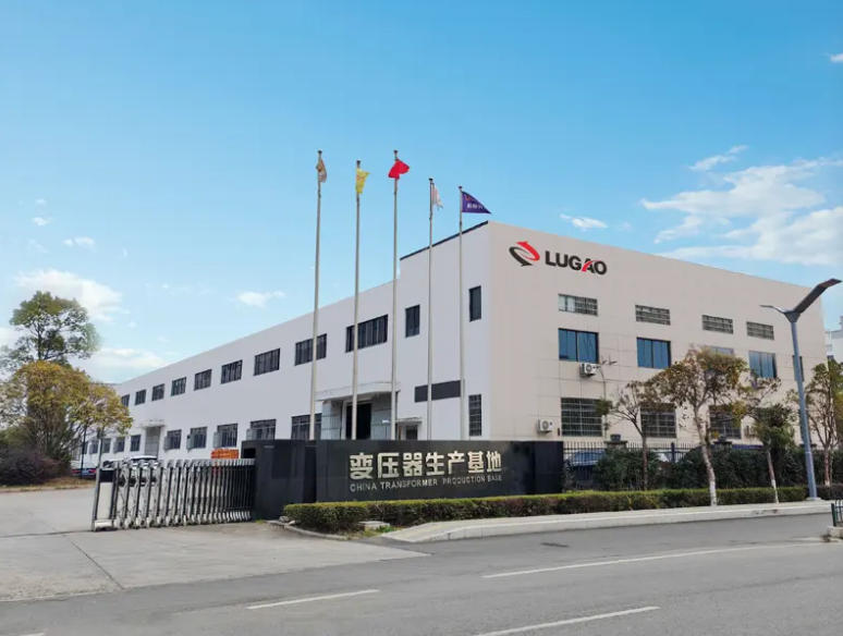
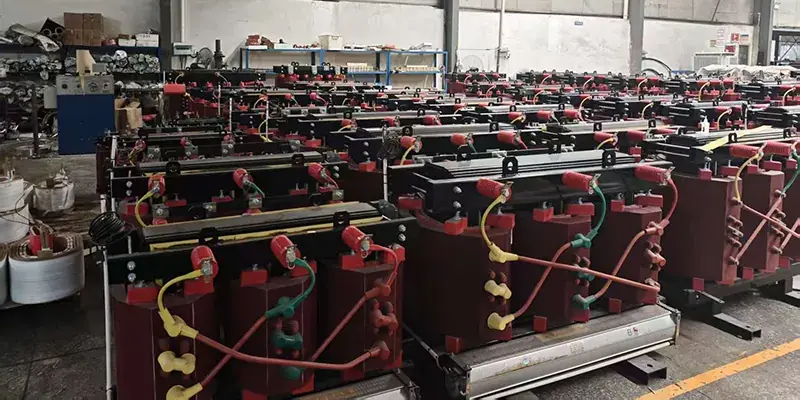
Lugao Power

Figure 4 — Lugao Power Co., Ltd. Manufacturing Facility


11.2 Switchgear Product Portfolio

Product Voltage / Current Range Standards Certifications
LV Main Distribution Board (MDB) Up to 1,000 V / up to 6,300 A IEC 61439-1/-2, GB CE, ISO, CCC
LV Motor Control Centre (MCC) Up to 1,000 V / up to 4,000 A IEC 61439-4, IEC 60947 CE, ISO, CCC
MV Metal-Enclosed Switchgear 3.6 kV – 40.5 kV / up to 4,000 A IEC 62271-200, GB/T 3906 CE, ISO, CCC, Type-Tested
Ring Main Unit (RMU) 12 kV – 40.5 kV IEC 62271-200, IEC 62271-1 CE, ISO, CCC, Type-Tested
Fully Insulated Metal-Enclosed Cabinet 12 kV – 40.5 kV / up to 4,000 A IEC 62271-200 CE, ISO, Type-Tested
HV Switchgear 3,600 V – 40,500 V / up to 4,000 A, 50 kA IEC 62271-100/-1, ANSI C37 CE, ISO, CCC, Type-Tested
Custom / OEM Switchgear Per customer specification IEC / ANSI / GB / BS (per project) Per project requirement

Table 14 — Lugao Power Switchgear Product Portfolio


11.3 Core Competitive Advantages

  • Complete Voltage Range: Single-source supply of LV, MV, and HV switchgear ensures design consistency, compatible protection coordination, and streamlined documentation. Eliminates interface management complexity between vendors.
  • Multi-Standard Compliance: Products designed and type-tested to IEC, ANSI/IEEE, GB, CE, and CCC standards. Enables deployment in almost any project jurisdiction — from Europe to North America to Asia-Pacific.
  • Strong Engineering & Customisation: In-house engineers provide custom configurations: non-standard voltages, unusual current ratings, special enclosure dimensions, unique busbar arrangements, relay integration, and SCADA interfaces.
  • Third-Party Inspection Support: Lugao supports FAT with customer representatives or inspection agencies, providing full test data, calibration records, and material certificates.
  • OEM Manufacturing Capability: Full OEM support: custom nameplates, colour schemes, documentation language, and packaging per brand specification. Proven export track record.
  • Global Export Experience: Extensive international shipping, customs documentation, and utility approval experience across Asia-Pacific, Middle East, Africa, Europe, and the Americas.


12. Quality Assurance & Testing


12.1 Quality Management System

Lugao Power's manufacturing and engineering operations are certified to ISO 9001, with a Quality Management System (QMS) covering all phases of product realisation — from incoming material inspection through manufacturing process control, finished product testing, and post-delivery support. The QMS includes controlled procedures for design review, supplier qualification, calibrated test equipment management, non-conformance processing, and corrective action.


12.2 Type Testing

Type testing — conducted on prototype units at accredited third-party high-voltage testing laboratories — verifies that the design meets all specified performance requirements. Lugao's standard product lines are type-tested in accordance with applicable IEC and GB standards. Type test reports from recognised laboratories (including KEMA, TÜV Rheinland, SGS, CPRI, and CEPRI) are available for review as part of the pre-qualification documentation package.


Type tests for MV switchgear (IEC 62271-200) include:

  • Dielectric type tests: Power frequency withstand voltage, lightning impulse withstand voltage.
  • Short-circuit making and breaking tests on circuit breakers.
  • Short-time withstand current test on busbars and enclosure.
  • Internal arc classification (IAC) test — verifying personnel safety under internal arc fault conditions.
  • Environmental tests: Temperature rise, IP protection class verification, vibration, seismic (where required).


12.3 Routine Testing

Routine Test Standard / Acceptance Criteria
Power Frequency Withstand Applied voltage at rated insulation level for 1 minute — no flashover or disruptive discharge
Insulation Resistance Megger test at 2.5 kV or 5 kV DC; result compared to baseline and minimum acceptance threshold
Mechanical Operation Test Circuit breaker and disconnector operating mechanisms cycled; operating times and travel measured
Interlocking Verification All safety interlocks (mechanical and electrical) verified to prevent incorrect switching sequences
Protection Relay Functional Test All configured protection functions tested against relay settings; trip times verified to specification
Wiring & Control Circuit Check All control and secondary wiring continuity, polarity, and insulation verified against approved drawings
Visual & Dimensional Inspection All components, labelling, busbar markings, and connections verified against approved manufacturing drawings

Table 15 — Lugao Power Routine Test Programme for Switchgear


QUALITY COMMITMENT

Every Lugao Power switchgear shipment is accompanied by a complete technical documentation package: routine test report with all measured values and acceptance criteria, type test certificate references, material certificates, calibration records for test equipment, dimensional inspection records, and as-built drawings. Third-party inspection and witnessed FAT can be arranged upon request.


13. Conclusions & Recommendations


13.1 Key Conclusions

  • Switchgear is a fundamental, safety-critical component of every power system. Incorrect specification, inadequate fault current rating, or poor quality equipment represent serious risks to personnel, equipment, and continuity of supply.
  • The switchgear industry is undergoing its most significant technology transition in decades, driven primarily by the regulatory phase-out of SF₆ insulating gas and the integration of digital intelligence and smart grid communication capability.
  • Vacuum and solid-insulated MV switchgear now represent technically proven, commercially available SF₆-free alternatives for the full MV voltage range. Projects with long asset lifetimes should strongly consider these technologies to avoid future regulatory compliance costs.
  • Short-circuit analysis is the safety-critical foundation of all switchgear sizing decisions. Switchgear must be rated for the maximum prospective fault current at the installation point, with appropriate safety margins.
  • Total cost of ownership analysis consistently reveals that higher-specification, better-quality switchgear delivers superior economic value over asset lifetimes of 20–30 years, compared to the apparent savings of lower-cost, lower-specification alternatives.
  • Lugao Power's complete LV-to-HV product range, multi-standard compliance, and strong engineering capability position it as a reliable, competitive single-source supply partner for switchgear projects across all voltage classes and global markets.


13.2 Strategic Recommendations

  1. Conduct or commission a rigorous power system short-circuit analysis at the design stage of any switchgear project. Do not rely on estimated or historic fault level data — system changes may have significantly altered actual fault levels.
  2. Specify SF₆-free technology (vacuum or solid-insulated) for all new MV switchgear projects unless a compelling technical justification exists for SF₆. This is especially important for projects with 20+ year asset lifetimes.
  3. Include IAC (Internal Arc Classification) requirements explicitly in MV switchgear specifications for all applications where personnel may be present near energised equipment.
  4. Mandate type test certificates from accredited third-party laboratories (not just factory test reports) as a non-negotiable requirement in all switchgear procurement RFQs.
  5. Evaluate total cost of ownership — not capital price alone — when comparing competing offers, particularly accounting for maintenance costs, SF₆ obligations, and energy losses.
  6. For projects requiring multiple voltage classes of switchgear, evaluate single-source procurement from a manufacturer like Lugao Power to simplify interface management, documentation coordination, and ongoing supplier relationship management.
Related News
Leave me a message
X
We use cookies to offer you a better browsing experience, analyze site traffic and personalize content. By using this site, you agree to our use of cookies.Privacy Policy
RejectAccept